
Oscilloskoper
Oscilloskoper – Visualisering og analyse af elektriske signaler
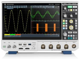
Oscilloskoper er måleinstrumenter, som benyttes specielt af elektronikindustrien til at synliggøre elektriske signaler som en kurve på en skærm. Kurven viser hvordan signalets spænding varierer med tiden. Et oscilloskop er en form for elektronisk test instrument, som tillader observation af konstant varierende signal spændinger.
Et oscilloskop er et elektronisk måleinstrument, der primært bruges til at visualisere og analysere elektriske signaler over tid. Det bruges ofte i elektronik, elektrisk ingeniørarbejde og forskning for at undersøge, måle og fejlfinde elektriske kredsløb og signaler.
Oscilloskoper fås i forskellige former og størrelser med forskellige funktioner og ydeevner. De kan variere fra små, bærbare enheder til store, avancerede laboratorieoscilloskoper afhængigt af brugerens behov og budget.

![]()
Leverandører af Oscilloskoper:
Elma Instruments A/S

Ryttermarken 2
3520 Farum
Telf.: 70 22 10 00
E-mail: info@elma.dk
HIN A/S
![]()
Langmarksvej 29
8700 Horsens
Tlf.: 76 25 90 90
E-mail: salg@hin.dk
PCE Instruments Denmark ApS
![]()
Birk Centerpark 40
7400 Herning
Tlf.: 70 30 53 08
E-mail: kontakt@pce-instruments.com
Rohde & Schwarz Danmark A/S

Lyskær 3D, 1.
2730 Herlev
Tlf.: 43 43 66 99
E-mail: info.rsdk@rohde-schwarz.com
Mere viden om et Oscilloskop:
Her er nogle af de grundlæggende funktioner og anvendelser af et oscilloskop:
- Signalvisualisering: Oscilloskopet viser elektriske signaler som grafer eller bølgeformer på en skærm. Dette gør det muligt for brugeren at se, hvordan signalet ændrer sig over tid.
- Måling af tid og spænding: Du kan bruge et oscilloskop til at måle parametre som signalernes frekvens, amplitude, periodicitet og tidsforsinkelser mellem forskellige signaler.
- Fejlfinding: Oscilloskoper er uundværlige værktøjer til fejlfinding af elektriske kredsløb. Ved at analysere signalerne kan du identificere unormale eller uønskede opførsler, såsom støj, forvrængning eller ustabilt signal.
- Karakterisering af signaler: Det er muligt at karakterisere komplekse signaler som f.eks. sinusoider, firkantbølger, trekantbølger og pulser ved hjælp af et oscilloskop.
- Verificering af design: Elektronikdesignere bruger oscilloskoper til at bekræfte, at deres kredsløb fungerer som forventet og opfylder specifikationerne.
- Undersøgelse af tidsafhængige fænomener: Oscilloskoper bruges til at studere og måle tidsafhængige begivenheder som f.eks. transienter, glitches, timingproblemer og støj i elektroniske kredsløb.
Her er nogle nøglepunkter om brug af et oscilloskop:
- Funktion: Oscilloskoper viser spændingsvariationer over tid på en skærm, hvor tid er vist på den vandrette akse (x-aksen) og spænding er vist på den lodrette akse (y-aksen).
- Typer: Der er forskellige typer oscilloskoper, herunder analoge og digitale. Digitale oscilloskoper er mere almindelige i dag på grund af deres fleksibilitet og evne til at behandle data.
- Kanaler: Oscilloskoper kan have en eller flere indgangskanaler. Flere kanaler tillader samtidig overvågning og sammenligning af flere signaler.
- Båndbredde: Dette angiver den maksimale frekvens af et signal, som oscilloskopet kan pålideligt måle. Det er en vigtig faktor at overveje, når man vælger et oscilloskop.
- Samplerate: Dette er antallet af målinger oscilloskopet tager pr. sekund. Det er afgørende for at opnå præcise målinger af højfrekvente signaler.
Flere væsentlige nøglepunkter:
- Triggersystem: Triggersystemet giver mulighed for stabilisering af det viste signal ved at synkronisere skærmen til et bestemt punkt på signalet.
- Automatisering: Moderne oscilloskoper har ofte indbyggede automatiseringsfunktioner til at forenkle målinger og analyse.
- Målefunktioner: Oscilloskoper kan udføre forskellige målinger såsom spænding, frekvens, stigetid, faldetid og meget mere.
- Probes: Prober bruges til at tilslutte oscilloskopet til kredsløbene under test og skal vælges omhyggeligt for at sikre nøjagtige målinger.
- Applikationer: Oscilloskoper anvendes til en lang række formål, herunder fejlfinding af elektroniske kredsløb, analyse af signalintegritet, kontrol af elektriske systemer og meget mere.


TME – Universelle Stäubli oscilloskop prober

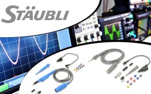
TME – Universelle Stäubli oscilloskop prober
Det anerkendte brand Stäubli er primært kendt som producent af højkvalitetskonnektorer, især til måleapplikationer. I dag omfatter leverandørens sortiment også et udvalg af oscilloskopprober, som for nylig er blevet tilføjet til TME’s katalog.
(Engelsk) Performing precise measurements with an oscilloscope largely depends on the quality of the probes used. The signal transmission from the measurement point to the device should be done with minimal, preferably negligible distortion. However, in many cases, this is not the only factor to consider during tests. Equally important is safety, which requires special attention when probing circuits with significant voltage, especially AC. The best examples here are power grid installations and devices powered by them.
Stäubli oscilloscope probes Stäubli are designed to allow such work, as well as with precision and compliance with commonly accepted standards, allowing them to be used with measurement devices from any manufacturer. These products belong to the Isoprobe II and Isoprobe III series.
We invite you to familiarize yourself with the new assortment.
In this article, we discuss topics such as:
- Safety and parameters of Stäubli oscilloscope probes
- Precise and interchangeable measurement tips
- Caps that help reduce interference
Oscilloscope probes
Stäubli probes meet the requirements of CAT III and IV standards in ranges up to 1000V RMS. This means they can also be used for testing electrical installations (e.g., taking measurements in network circuits and distribution boards) and devices such as industrial or consumer machines (RTV/AGD equipment). The design of the probes ensures proper insulation distances comply with IEC/EN 61010-031:2015 standard. Moreover, many of the supplier's probes can work with signals with a frequency exceeding 450MHz.
The manufacturer's assortment includes passive high-frequency (HF) test probes and accessories – it should be emphasized that most products are supplied with accessories included. These may include (depending on the chosen item):
- interchangeable, colored caps used to identify the tip;
- crocodile clips for ground connection;
- insulated clamps for wires;
- precise tips;
- caps.
All probes are equipped with insulated BNC connectors, i.e., plugs commonly used in oscilloscopes.


For electronics technicians and electricians testing waveforms in network circuits and connected devices, an important part of the offer are probes equipped with voltage dividers. They come in ratios of 10:1 and 100:1. They allow safe connection of circuits from the upper limit of low voltage (up to 1kV AC) to the inputs of standard oscilloscopes.
Measurement tips
A practical accessory for oscilloscope probes are caps with measurement tips. They allow changing the probe contact to one of the standards used in metrology. From the TME catalog, you can purchase 4-millimeter and 2-millimeter versions. The former have banana plug width, are compatible with such connectors, and thus with a range of other accessories, e.g., crocodile clips or multimeter sockets. The caps are available in several color variants and, like the probes, meet the CAT II 1000V standard requirements.


Cap with reference contact
The cap with a reference contact has an additional lead, the reference contact, connected to the measurement circuit ground and the shield of the cable and probe. Such a connection, placed close to the measurement tip, improves the accuracy of digital and pulse signal testing, characterized by high frequency, reducing distortion and noise, especially when using long cables. The contact of the cap has a relatively short lead, so it provides better results than the classic alternative, which is an auxiliary connection with a flexible wire and crocodile clip.
Transfer Multisort Elektronik – New Teledyne Lecroy T3DO1000HD Series Oscilloscopes
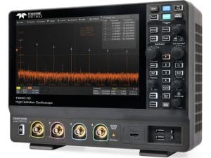
Transfer Multisort Elektronik – New Teledyne Lecroy T3DO1000HD Series Oscilloscopes
12-bit devices with digital protocol analysis function.
Recently, Teledyne Lecroy introduced new 12-bit T3DO1000HD series oscilloscopes. These products have already been added to the TME catalog, and customers can purchase them directly from our warehouses. Below we present a general overview of the devices.
The T3DO1000HD series includes 4-channel oscilloscopes supporting bandwidths up to 100MHz or 200MHz. The key advantages of the devices are the sampling rate, which reaches 2Gsps, and the maximum refresh rate of 120,000 wfm/s (in normal mode) or up to 500,000 wfm/s (in sequence mode). The memory length is up to 100Mpts, allowing the oscilloscopes to record unusual events with long waveforms.
LC-T3DSO1204HD
LC-T3DSO1204HD (200MHz)
LC-T3DSO1104HD
LC-T3DSO1104HD (100MHz)
Another important feature of Teledyne Lecroy equipment is the advanced software, which includes functionality for analyzing popular communication buses. Recognizable protocols include I2C, SPI, UART, CAN, LIN, CAN FD, and FlexRay. Triggering can occur in the standard way (rising and falling edges, time interval, etc.), as well as based on a video clock signal or serial bus. These capabilities greatly facilitate prototyping, development work, and servicing of diverse digital electronic circuits.
It is also worth noting that the T3DO1000HD series features a large, 10.1-inch touchscreen display. This makes operating the oscilloscope convenient and intuitive. The interface is designed for quick navigation between menu options, direct access to zoom in/out functions of the displayed waveform, and other basic analytical tools.
Of course, the presented oscilloscopes are equipped with communication interfaces (Ethernet and USB), which enable remote operation and data export to a computer.
| Characteristics | |
| Oscilloscope type | digital |
| Number of channels | 4 |
| Bandwidth | 100MHz or 200MHz |
| Sampling | 2Gsps |
| Memory record length | 100Mpts/ch |
| Type of display used | LCD TFT 10.1" |
| Trigger modes | automatic, normal, single |
| Time base | 1n...1ks/div |
| Max input voltage | 400V |
| Vertical resolution | 12bit |
| Manufacturer series | T3DSO1000HD |
| Rise time* | 1.8ns or 3.5ns |
| Input impedance | 1MΩ/17pF |
| Dimensions | 317.2x236x149mm |
| Display resolution | 1024x600 |
| Touch panel | yes |
* depending on the model


